~ 24 min
How to Make a Cloud Chamber
Step by Step Instructions to Build a Cloud Chamber
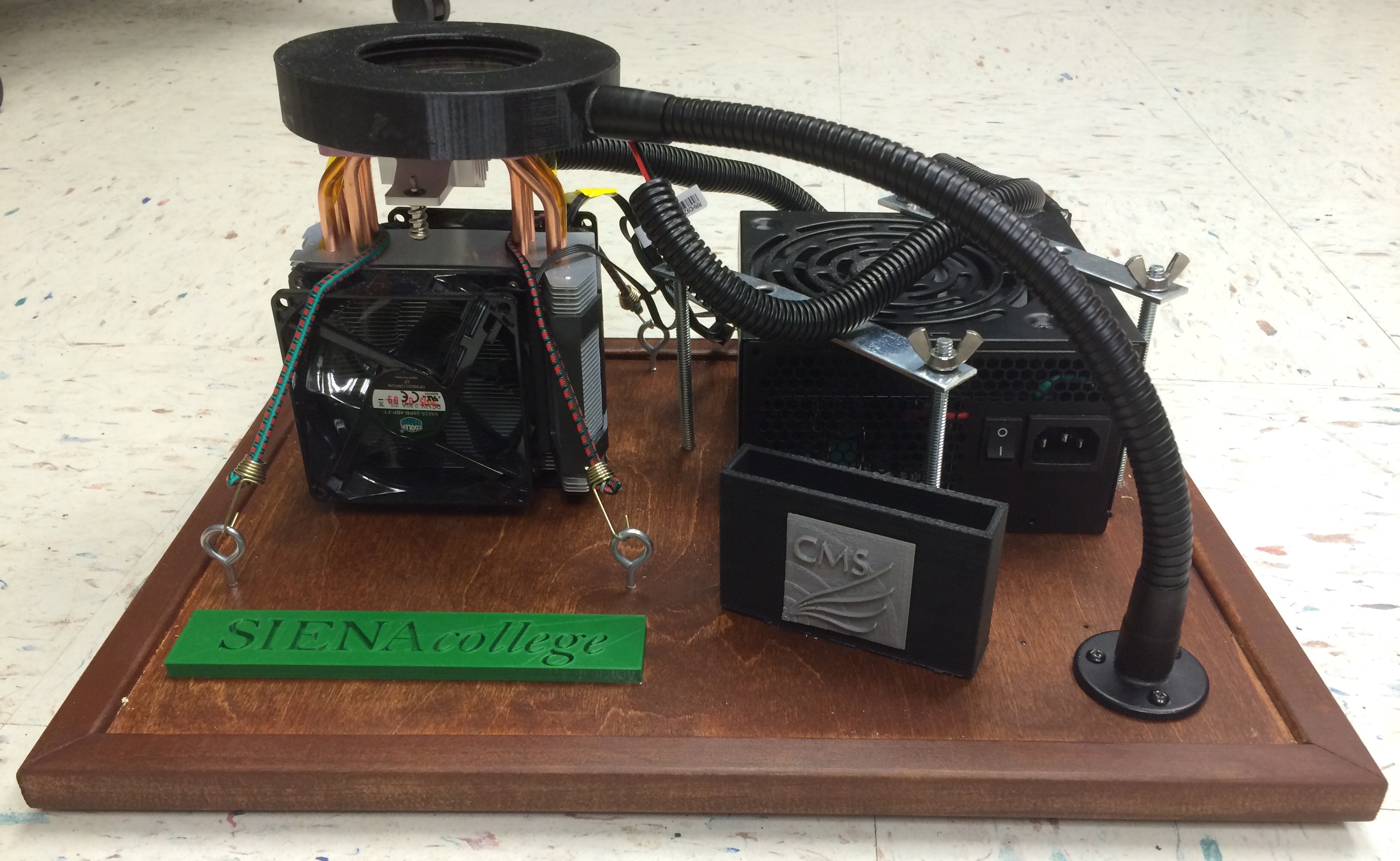
Insert picture of finished product
To streamline productivity it is best to do the following before starting to build the cloud chamber:
- Gather all the materials and tools needed
- 3D print any 3D printed parts (Steps 31, 32, 64)
- Soak The Absorber in water and let it dry and attach it to the petri dish (Steps 30-33)
- Put together the mounting board with the trim, stained and finished (Steps 43-48)
Step 1: Spray paint the bottom outside of the petri dish lid (the one with the bigger diameter) black and put it to the side to let it dry with the spray painted surface facing up. Make sure to put enough spray paint on so you cannot see through the petri dish. Place the other part of the petri dish with the surface facing up so that it is not touching anything to avoid getting scratched.
Step 2: You have to convert the power supply to a lab bench power supply so that when you press the switch it will turn on. DO NOT PLUG THE 430 WATT POWER SUPPLY IN. Cut the mesh wire organizer of the 24 pin connector to be about 3 inches from the opening where the wires come out of the power supply (see Figure 1).
- NOTE: It may be easier to cut the wires and mesh wire organizer right after the taped part on the mesh wire organizer by the adapter first, and then cut the mesh wire organizer the specified length.
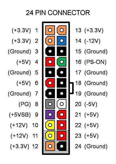 Figure 1. Diagram of 24-pin connector (figure from Instructables)
- NOTE: WHEN SOLDERING/CUTTING ANY WIRES DO NOT HAVE THE POWER SUPPLY PLUGGED IN.
Step 3: Cut the needed wires (every wire except Yellow Wire 3) of the 24 pin adapter the specified lengths (see below). Then cut the extra wires to be around the same length as the mesh wire organizer.
The lengths below are best for the optional mounting of the cloud chamber that is described at the end of the instructions. If you do not plan to mount the parts of the cloud chamber then you can adjust the wire lengths as you see fit.
Lengths of each wire (from where they come out of the power supply to the end of the stripped part of the wire):
- Black wire 1 (connected to the CPU Cooler with 4 pin adapter): 6 1/4 inches
- Black wire 2 (connected to Green Wire 1): 1 inch longer than the cut mesh wire organizer (same length as Green Wire 1)
- Black wire 3 (connected to the black wire on the 12710 peltier): 9 inches
- Black wire 4 (connected to the black wire on the 12709 peltier): 9 inches
- Black wire 5 (connected to the black wire on LED strip): 16 1/2 inches (when the black wire from the LED strip is about 5 3/4 inches)
- Yellow Wire 1 (connected to the CPU Cooler with 4 pin adapter): 6 1/4 inches
- Yellow Wire 2 (connected to the red wire on the 12710 peltier): 9 inches
- Yellow Wire 3 (connected to the red wire on LED strip): 14 inches (when the red wire from the LED strip is about 5 3/4 inches)
- Red Wire 1 (connected to the red wire on the 12709 peltier): 9 inches
- Green Wire 1 (connected to black wire 2): Same length as Black Wire 2
Step 4: You will need 3 yellow wires so cut another mesh wire organizer with a yellow wire in it to be 2 inches from the opening where the wires come out of the power supply. Cut Yellow Wire 3 the specified length, found in Step 3. Cut the other wires that are not needed around the same length as the mesh wire organizer.
Step 5: Strip the end of the 5 black wires, 2 yellow wires, 1 red wire, and 1 green wire from the 24 pin adapter from the power supply to be about 1/2 inch. Also strip the end of Yellow Wire 3 from the other group of wires in the power supply about 1/2 inch. Make sure none of the stripped parts of different color wires touch.
Step 6: From the 24 pin adapter, use electrical tape to group together like colored wires that are not needed (the ones that are not listed in Step 3). Make sure the electrical tape covers the end of the wires where you cut them.
Step 7: Solder Black Wire 2 and Green Wire 1 together. Then put electrical tape around them. Make sure no other stripped wires are touching different color wires.
- NOTE: Click here to learn how solder wires together and then put heat shrink over the wires. Applying the heat shrink will be necessary for the other wires later on. For now just pay attention to how to solder wires together and instead of putting heat shrink over the stripped part of the wires, just put electrical tape over them.
Step 8: Now use a zip tie to group together all the wires from the 24 pin adapter and the mesh wire organizer. Put the zip tie right before the end of the cut mesh wire organizer. Tape around the mesh wire organizer, zip tie and wires all together with electrical tape (See Figures 2 and 3).
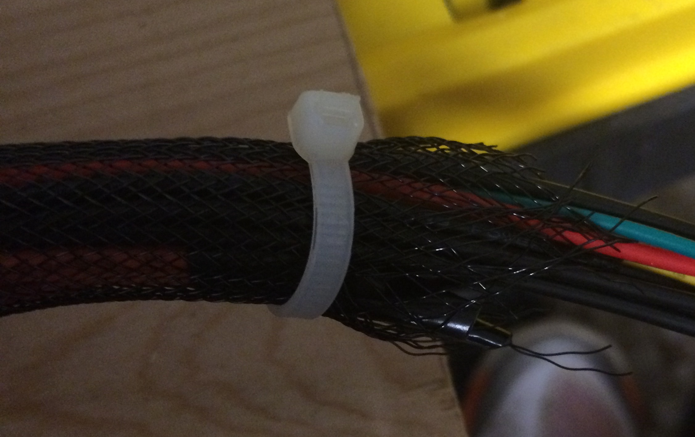 Figure 2. Zip tie around mesh wire organizer and wires
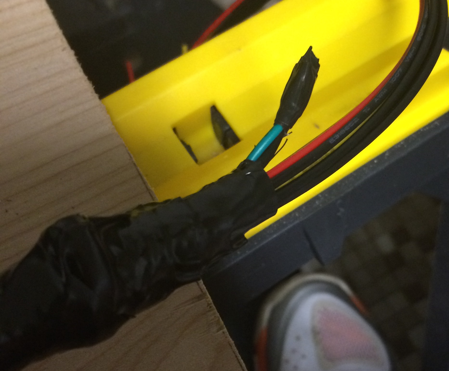 Figure 3. Taped wires in mesh wire organizer
Step 9: Repeat Steps 6, 7 and 8 for the other adapter with Yellow Wire 3.
Step 10: Cut the other mesh wire organizers to be about 1 or 2 inches from the opening where the wires come out of the power supply.
- NOTE: It does not matter what length it is. We cut the mesh wire organizers a smaller length for aesthetics.
Step 11: Cut the wires to be about the same length of the mesh wire organizers and repeat Steps 6, 7 and 8 for the rest of the wire adapters that are not needed. You can use electrical tape to tape together like colors from the rest of the groups of wires that are not used. Once you put the tape around each group of unneeded wires, put a zip tie around all of them (look at Figure 4).
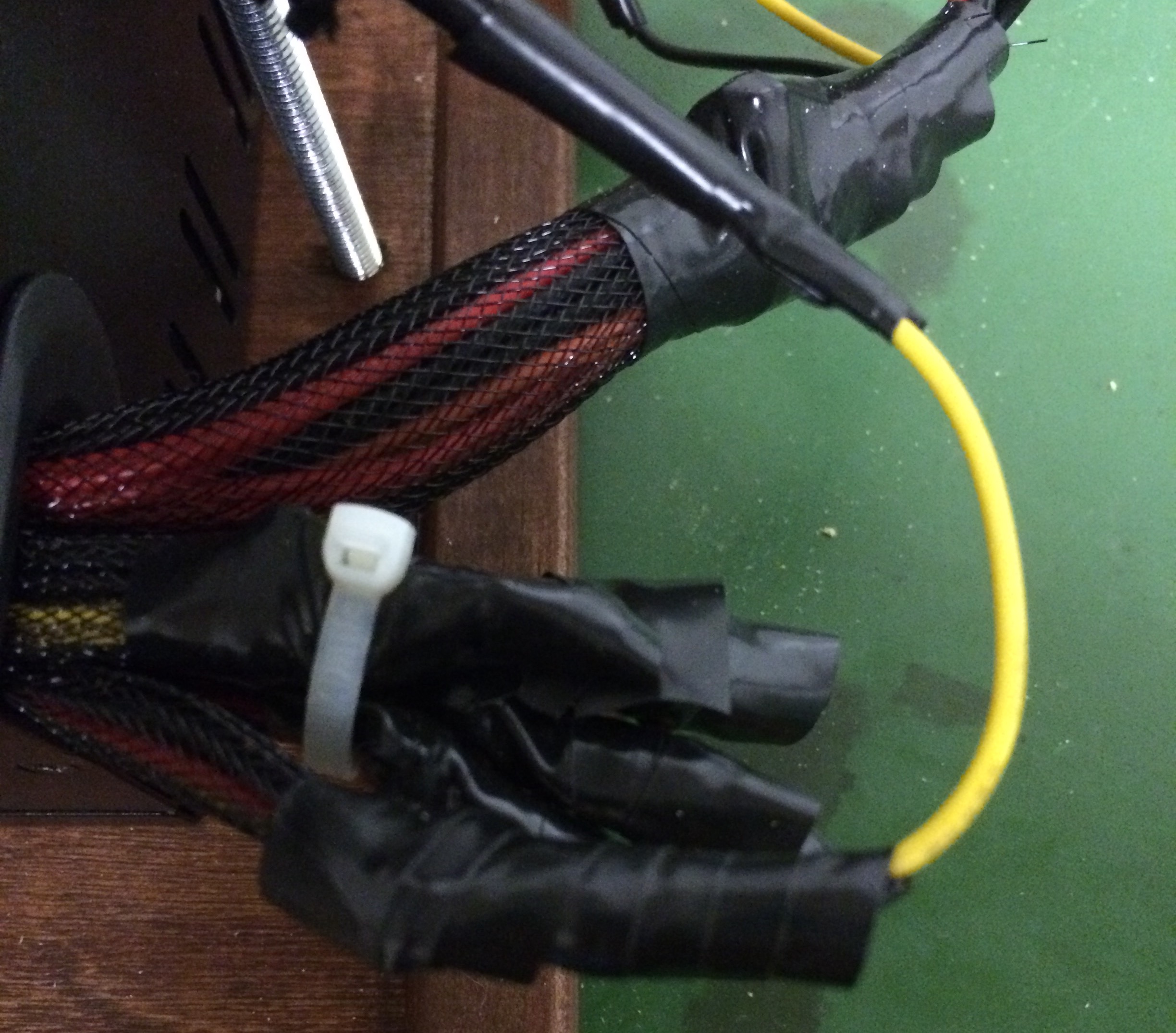 Figure 4. Finished grouping of wires from power supply
Step 12: Make sure no stripped parts of different color wires are touching. Plug the power supply in and turn it on to make sure that the fan works. Turn it off and unplug it afterwards.
Step 13: Once the fan works on the power supply, place the CPU Cooler (Cooler Master Hyper D92) so that the pipes are on your left and right side and the fan is facing you as you are facing the CPU Cooler (see Figure 5). Also make sure the wire with the 4 pin adapters from the CPU Cooler is on the side of the CPU Cooler closest to the power supply.
Step 14: Slide heat shrink down Yellow Wire 2 and Black Wire 3 before soldering. Look to the note in Step 7 to learn how to solder wires and apply heat shrink over the stripped soldered parts of the wires. You will be using heat shrink for the rest of the wires you solder together.
Step 15: Solder Yellow Wire 2 (12V) to the red wire on the 12710 peltier and solder Black Wire 3 (ground) to the black wire on the peltier.
Step 16: Put a thin layer of the thermal paste on the top surface of the CPU cooler. The thermal paste should cover the same area that the peltier will cover. You do not need a lot of thermal paste.
- NOTE: You can squirt the thermal paste onto the surface and then spread with a credit card like piece. Make sure the area is covered, but use the thermal paste sparingly.
Step 17: Put the 12710 peltier on top of the thermal paste so that the wires are perpendicular to the pipes on the CPU cooler. The red wire on the peltier should be on your right as you are facing it, as shown in Figure 5.
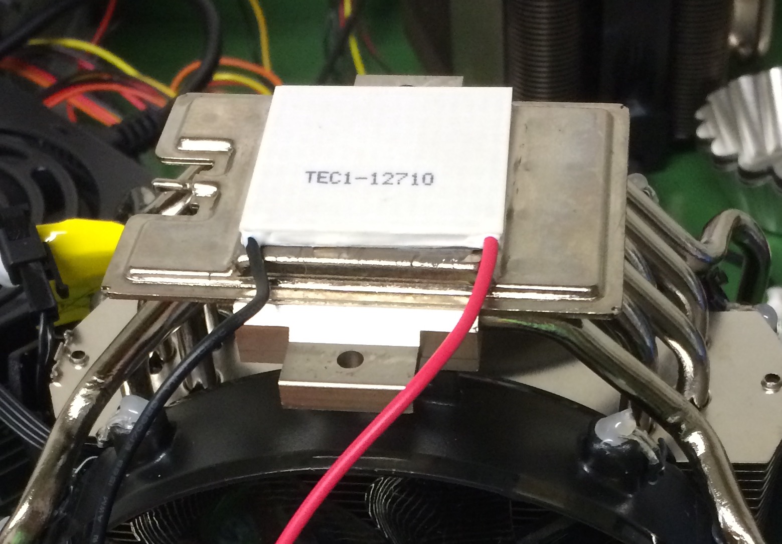 Figure 5. Placement of 12710 peltier on the CPU cooler
Step 18: Press the peltier down and move it around slightly so that you know it has good contact with the thermal paste.
Step 19: To test if you put on the peltier correctly, turn on the power source and touch the top of the peltier. If the peltier is hot, unplug it immediately, you have put the peltier on wrong. If it is cold you did it correctly. Unplug the power source.
Step 20: To connect the power supply to the CPU Cooler, you should cut four 1 1/2 inch (measurement includes 1/2 inch striped parts) connector wires that are stripped at both ends. These will connect the two 4 pin adapters from the CPU Cooler to the power supply. Figure 6 shows you where to connect the yellow and black/white/grey wires in the 4 pin adapters. In the HYPER D92 CPU Cooler you will need to solder and put heat shrink on 2 half inch connector wires to Yellow Wire 1. Then do the same for Black Wire 1 because there are two 4 pin adapters (we suggest using 2 yellow connector wires to connect to Yellow Wire 1 from the power supply and 2 black connector wires to connect to Black Wire 1 from the power supply to make things less confusing).
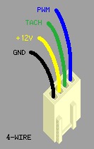 Figure 6. Picture of 4 Pin PWM coming from the CPU cooler (figure from overclock.net)
Step 21: Plug in and turn on the power supply to make sure the fans work on the CPU cooler. Unplug the power supply after.
Step 22: Solder and put heat shrink on Red Wire 1 (5V) from the power supply to the red wire on the 12709 peltier and solder and put heat shrink on Black Wire 4 (ground) from the power supply to the black wire on the 12709 peltier.
Step 23: Put a thin layer of thermal paste, like before, on the top of the 12710 peltier and place the 12709 peltier on top of it with the red wire on the right side as you are facing it, pushing down on it. The red wire on the 12709 peltier should be on the same side as the red wire on the 12710 peltier.
Step 24: To test it, turn on the power supply and touch the top of the peltier. If it is hot unplug it immediately, you have put the peltier on incorrectly. If it is cold you did it correctly. Unplug the power supply.
Step 25: You can contact us by email (as25glea@siena.edu) to request project panel pieces, or you can cut them yourself. Use a hot wire cutter to cut 3 pieces of project panel to keep the peltier in place on the CPU cooler. Figure 7 shows the dimensions for the project panel.
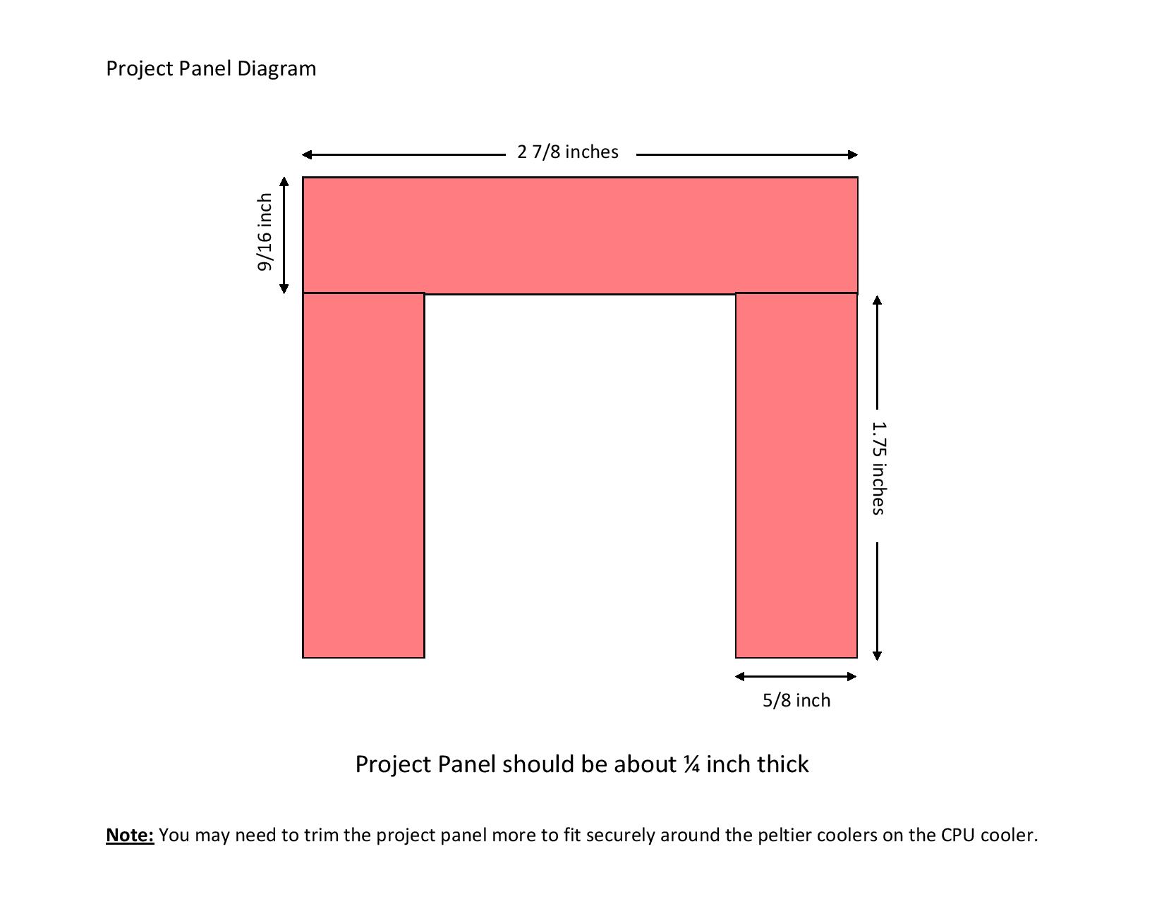 Figure 7. The dimensions of each piece of project panel with the Cooler Master HYPER D92.
Step 26: Position the 3 pieces of project panel around the peltier coolers so that there is an opening in the wires. The project panel should be the same level as the peltier coolers (look at Figure 8). Make sure it fits nicely around the peltier coolers. Now hot glue the 2 shorter pieces to the longer piece and lay them around the peltier. You may need to adjust the sizing of the project panel.
Step 27: Cut a piece of kapton tape and place it over the peltier coolers to keep them in place. For the HYPER D92 CPU Cooler you should only use one piece of tape and have it lay perpendicular to the wires from the peltier and wrap it around one of the pipes on each side (shown in Figures 8 and 9).
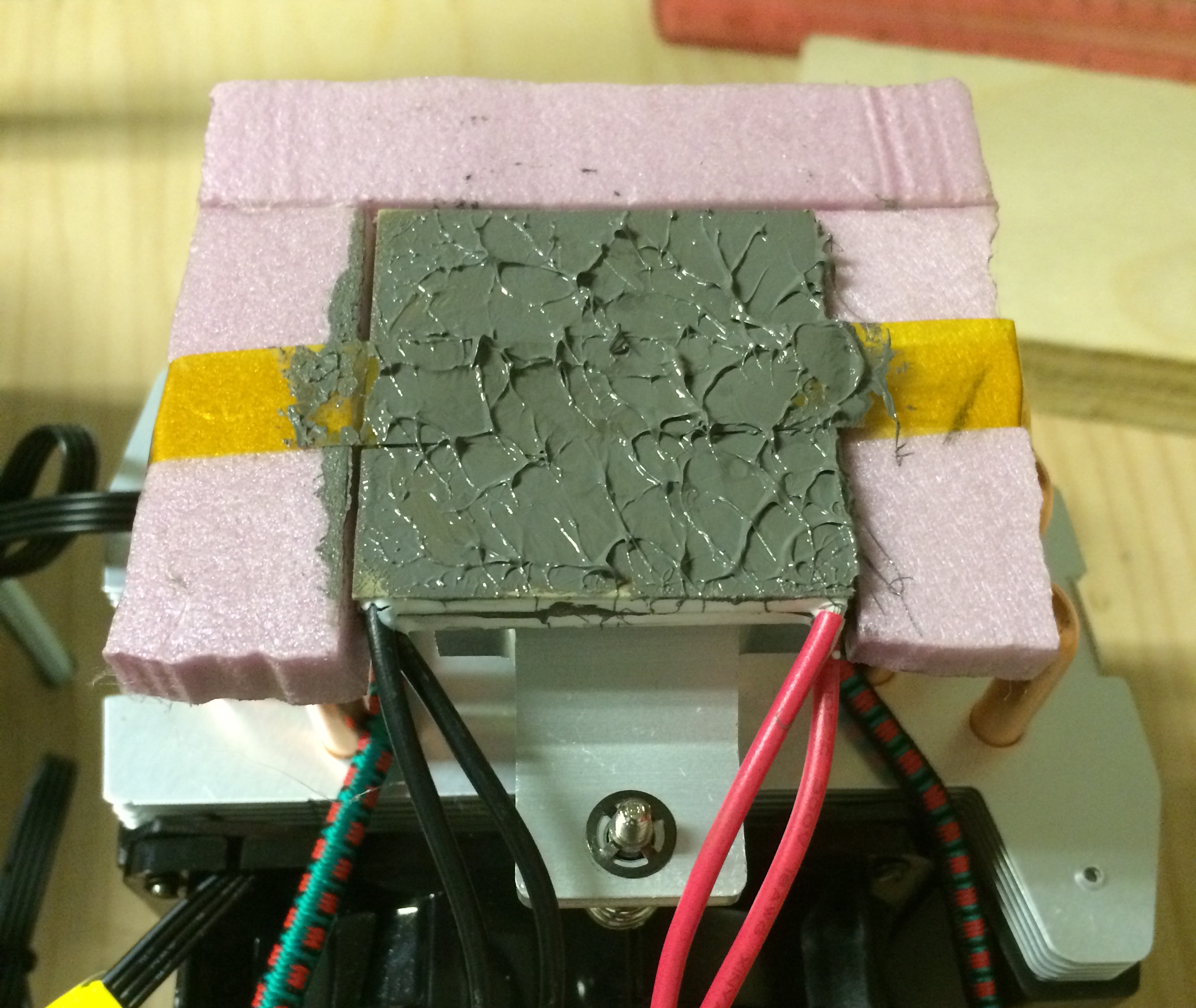 Figure 8. Both peltier coolers placed on the surface of the CPU cooler with the project panel around it, along with a piece of kapton tape applied over everything.
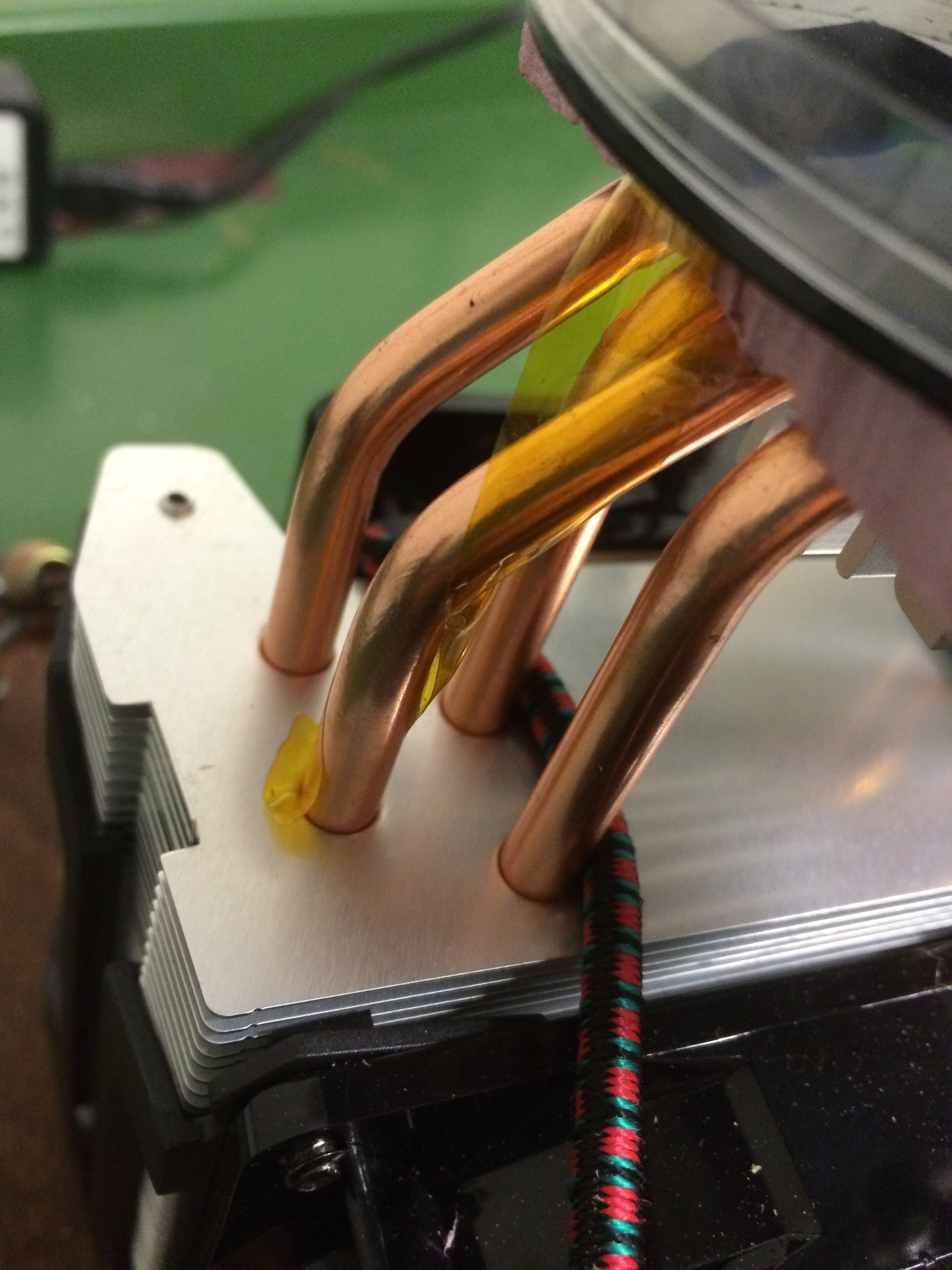 Figure 9. This shows how the kapton tape should be applied around the pipes on the CPU cooler.
Step 28: Apply thermal paste on top of the peltier and kapton tape (this should be thicker than what was previously done).
Step 29: Put the spray painted lid of the petri dish on top of the peltier with the thermal paste and press down to assure it has good contact (spray painted side has contact with the thermal paste).
Step 30: Soak The Absorber in water and let it dry before using it.
Step 31: If you have a 3D printer, you can download the stl file of the absorber weight (click on the Raw button to download when you go to the link) or contact us through email (as25glea@siena.edu) to request to have us send you a 3D printed absorber weight. Trace it onto The Absorber (when it is dry).
Step 32: If you have a 3D printer, you can download the stl file of the LED Holder (click on the Raw button to download when you go to the link) or contact us through email (as25glea@siena.edu) to request to have us send you a 3D printed LED holder. Trace the circle on the inside of the LED holder on the inside of the circle you traced from the absorber weight. Cut a hole in the center of the circle you traced so that you can make a ring (see Figure 10).
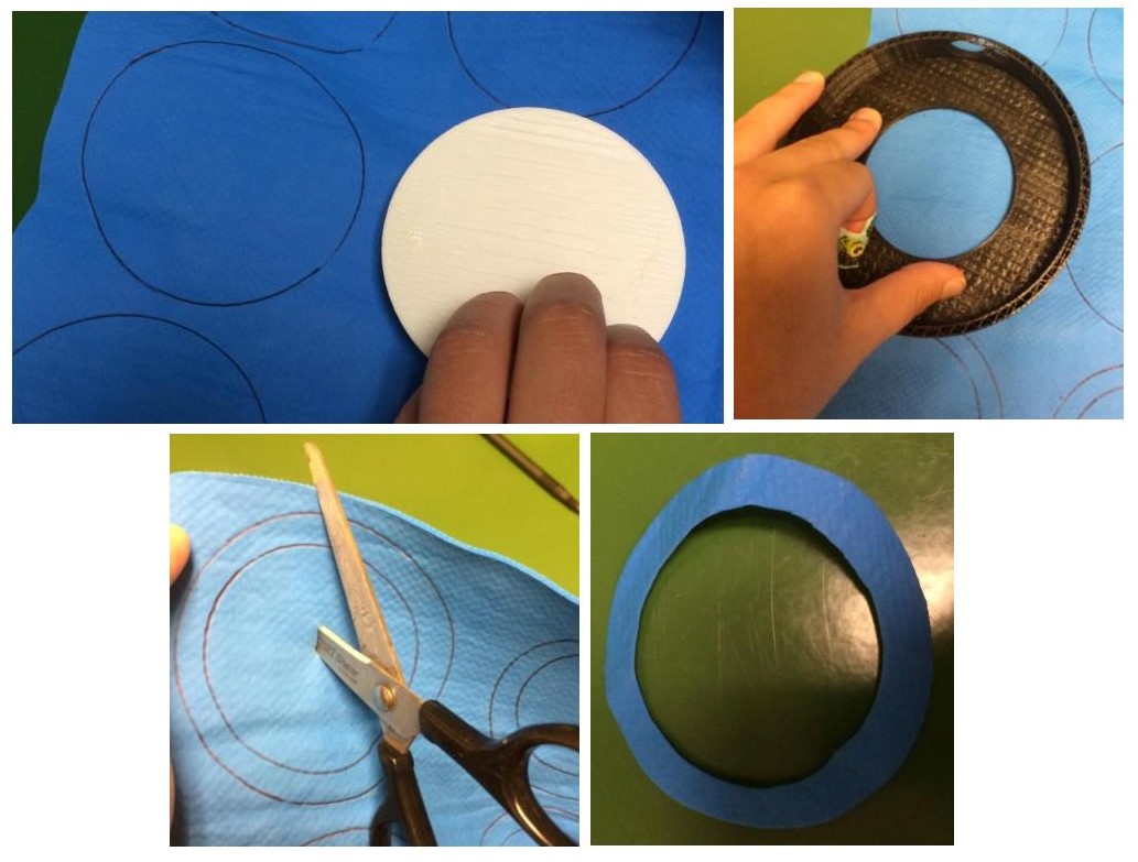 Figure 10. Process of creating the ring of The Absorber to attach to the inside of the petri dish lid.
Step 33: Wet The Absorber ring you just cut. It should not be dry. When attaching it to the inside of the petri dish, place the petri dish on a glasses cleaner cloth or piece of printer paper so it is not scratched. We put epoxy on a piece of left over wood and used a popsicle stick to mix it and then applied it to the petri dish. Put a thin layer of epoxy with a popsicle stick on the inside outer edge of the petri dish without the spray paint. Place the wet The Absorber ring on the epoxy in the petri dish. Then put the 3D printed absorber weight on top of it with a textbook (or something similar in weight) on top of the absorber weight. This will ensure The Absorber ring dries flat on the petri dish. It will take about 3-4 days to dry.
Step 34: Once you have the 3D printed LED holder, take the LED strip and wrap it around the inside and mark where it should be cut (on our LED strip from Radio Shack every 3rd LED there was a scissor marker where you could cut so we had 18 LEDs, which was a little less than 12 inches).
- NOTE: You should put the red and black/white/grey wires from the LED strip through the small hole from the inside of the LED holder and then wrap it around the inside of the LED holder. If you need to solder wires to the LED strip, follow the instructions given on how to do this in the package of LED strips you have and make the connector wires to be 5 3/4 inches.
Step 35: Cut the LED strip where it is needed and use epoxy to attach the LED strip to the inside of the LED holder. We put epoxy on a piece of left over wood and used a popsicle stick to mix it and then applied it to the back of the LED strip. Then we put it on the inside of the LED holder right at the edge of it and used binder clips to hold the LED strip in place until it dried (see Figure 11).
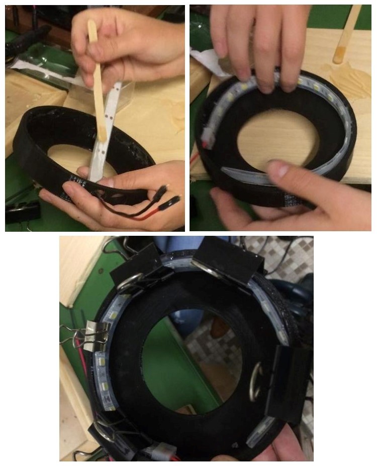 Figure 11. Attaching the LED strip inside of the 3D printed LED Holder.
Step 36: Solder and apply the heat shrink to the red wire coming from the LED strip once it is secured and the epoxy is dry in the LED holder with the wires already through the wire hole to Yellow Wire 3. Also solder and apply the heat shrink the black/white/grey wire from the LED strip to Black Wire 5.
Step 37: Make sure all the wires that are in use are soldered with heat shrink/electrical tape over them. Now you can plug in the power supply and turn it on to make sure the fan in the power supply, fans on the CPU cooler, and the LEDs work. Once everything works, turn the power supply off.
Step 38: Make sure that nothing is in the path of the fans on the CPU Cooler. Check to make sure the peltier coolers are aligned on the CPU Cooler as well.
Step 39: Put 1mL of 99% alcohol evenly across the felt ring using an eyedropper.
Step 40: Take the radioactive source and place it on the bottom inside of the spray painted petri dish and then put the cover with the felt ring over it.
Step 41: Rest the LED holder over the petri dish.
Step 42: Turn on the power supply, and within 30-60 seconds you will see the trails, as shown in Figure 12.
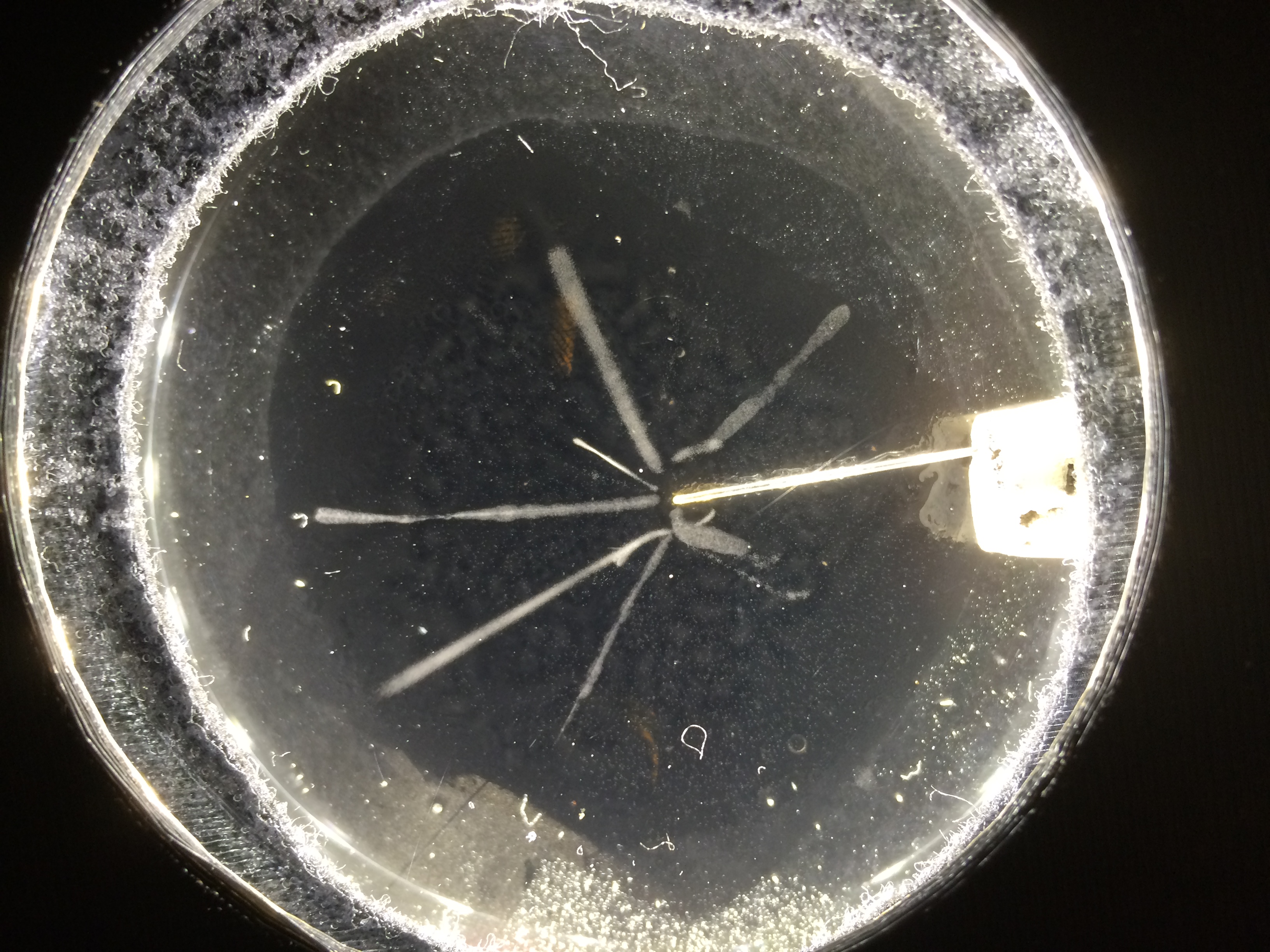 Figure 12. Picture of trails.
The following steps are optional. If you want to mount the materials needed for the cloud chamber and make it look more professional, please continue with the instructions.
Step 43: Cut the birch plywood 12 inches x 16 inches with a circular saw for a clean cut.
- NOTE: Use a guiding rail and a woodworking square to make a straight cut through the plywood. It is also best to have the side you will not be mounting everything on facing up when you cut the plywood with the circular saw (see Figure 13).
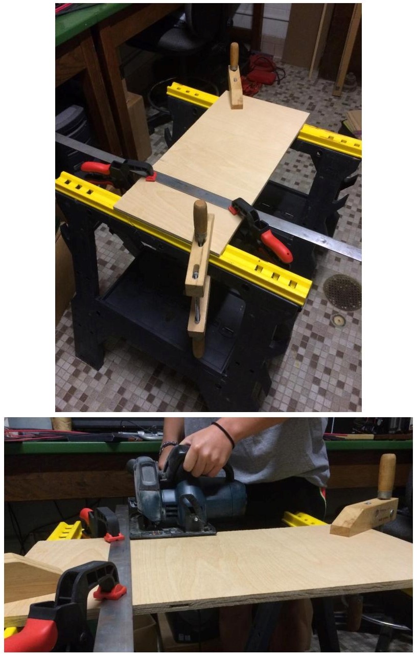 Figure 13. Set up of using the circular saw to cut a straight edge on the plywood.
Step 44: Cut the trim into 2 pieces that are 11 1/4 inches (from inner part to inner part) and 2 pieces that are 15 inches (from inner part to inner part) with a miter saw (look at Figure 14). Make sure they fit around the plywood and match up in all four corners. If they do not, adjust and cut/sand accordingly. If there are small gaps in the corners where they meet you can use wood filler later on.
- NOTE: It may be best to cut the trim 1/2 inch longer than needed to leave room for error.
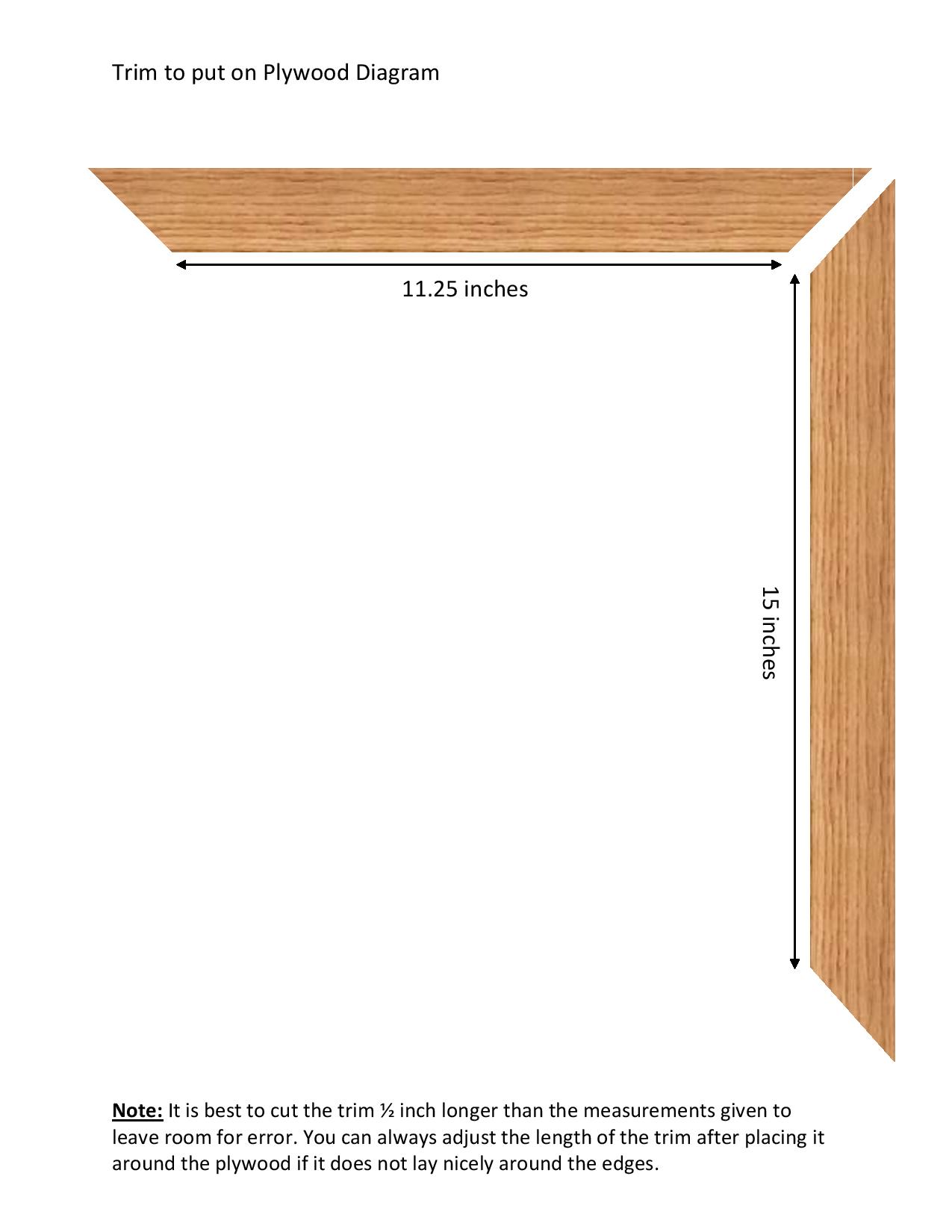 Figure 14. Dimensions of trim.
Step 45: Use a 3/32 inch drill bit and drill a hole in each corner of the plywood on the side that you will not be mounting everything on. DO NOT DRILL ALL THE WAY THROUGH THE PLYWOOD. Only drill about half way into the plywood. You do not want a hole showing on the other side of the board.
Step 46: Use a screw driver and twist the rubber feet screws into the 4 holes (look at Figure 15).
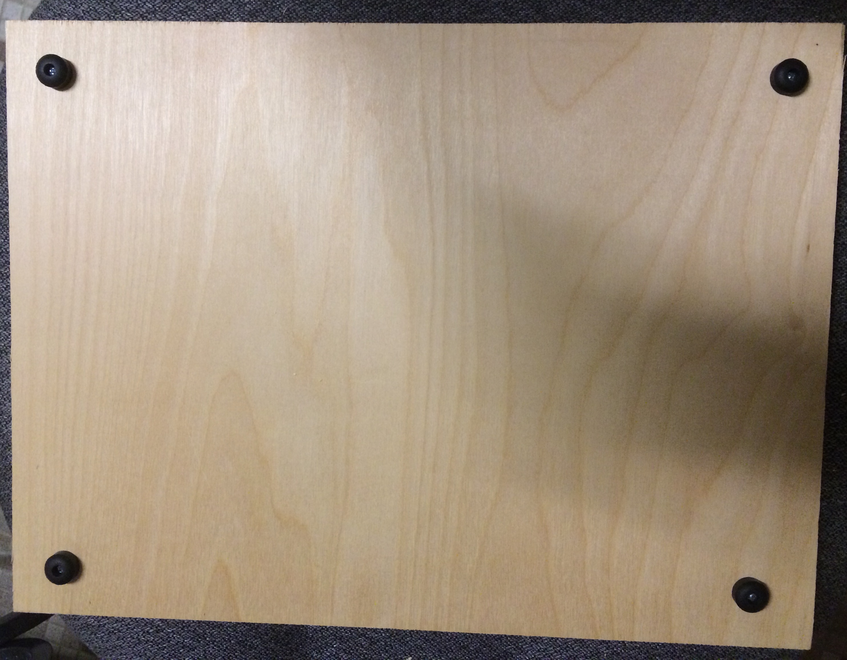 Figure 15. Picture of rubber feet screwed into the plywood.
Step 47: Now use wood glue to glue the trim on the plywood mounting board. Apply it to the edge of the plywood so that there is not a lot of glue that seeps over onto the visible part of the plywood once the trim is put on (see Figure 16). The trim should be able to rest on the plywood without falling off before you put the glue on. Once you position the trim around the plywood, if you notice any excess glue use a wet cloth to wipe it off. Place something heavy, like a textbook, over the trim on each corner to keep it in place while the glue dries.
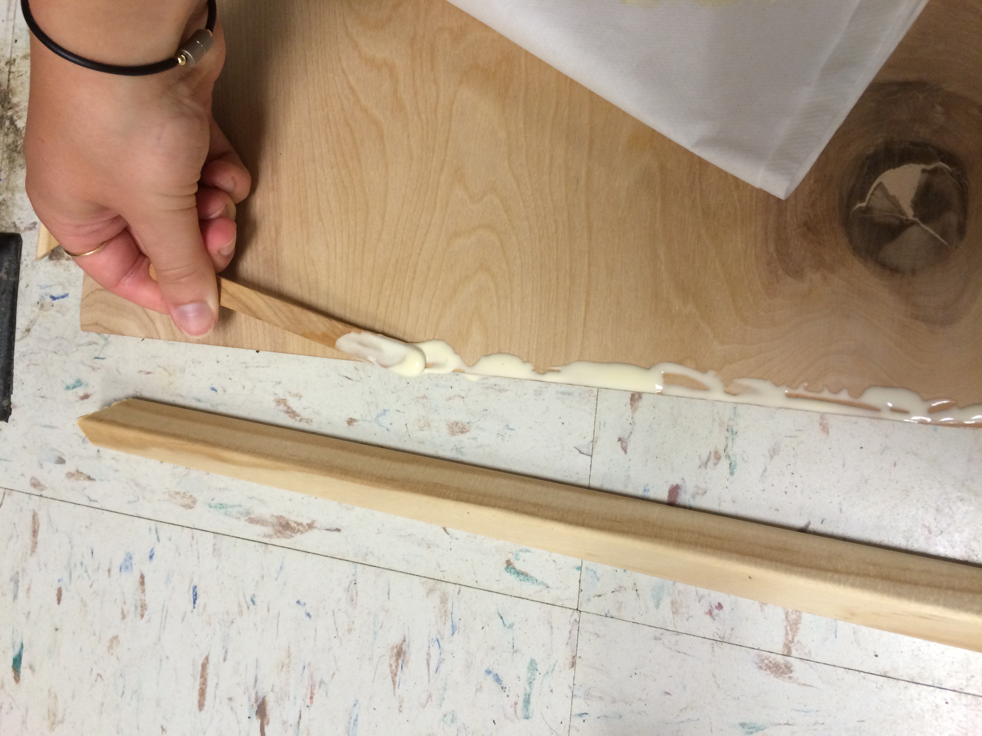 Figure 16. Application of wood glue onto the plywood for the trim to be put over.
Step 48: Once the glue is dry, if wood filler is necessary, apply it to the corners.
Step 49: Use the Template for Mounting the Cloud Chamber (see Figure 17) to see where to position all the parts of the cloud chamber. Drill 4 holes using a 5/64 inch drill bit for the eye screws first. Then twist in the eye screws.
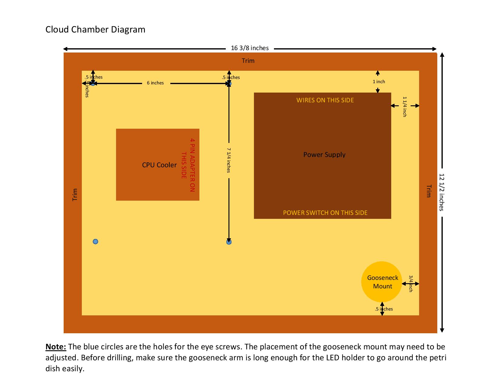 Figure 17. Template for Mounting the Cloud Chamber.
Step 50: Place the CPU Cooler in the middle of the 4 eye screws and secure it by using the 10” bungees (shown in Figure 18). The wires coming from the peltier coolers connected to the power supply should be on the opposite side of where the gooseneck will be.
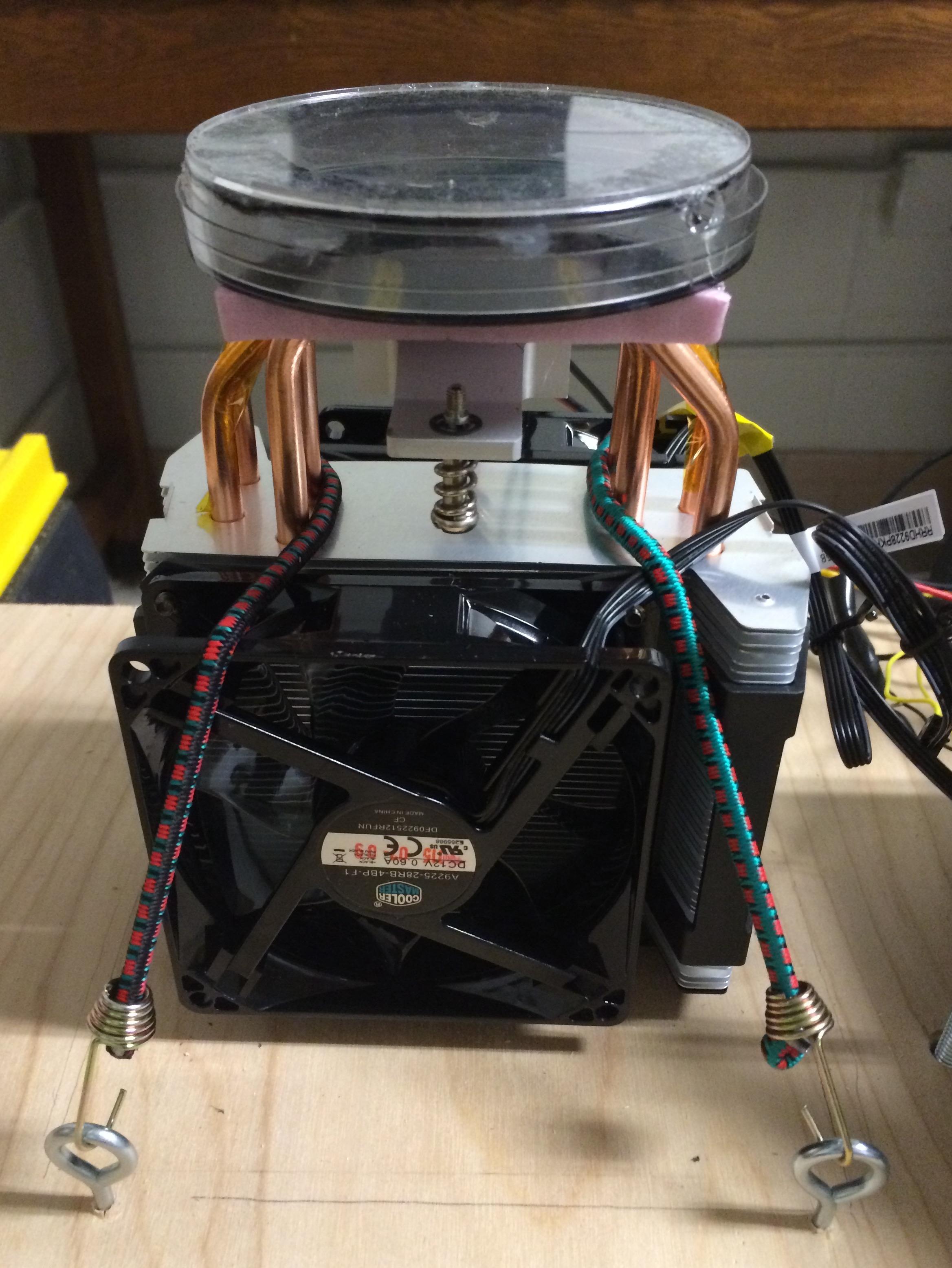 Figure 18. Showing how to mount the bungees
Step 51: Now place the power supply where it is shown on the template. The wires from the power supply to the CPU cooler should be on the opposite side of where the gooseneck mount will be placed. Put the 2 mending plates over the top right and bottom left corners of the power supply (see Figure 19). Make sure the mending plates are not covering the fan in the power supply. Use a pencil to mark where the holes for the bolts should be drilled.
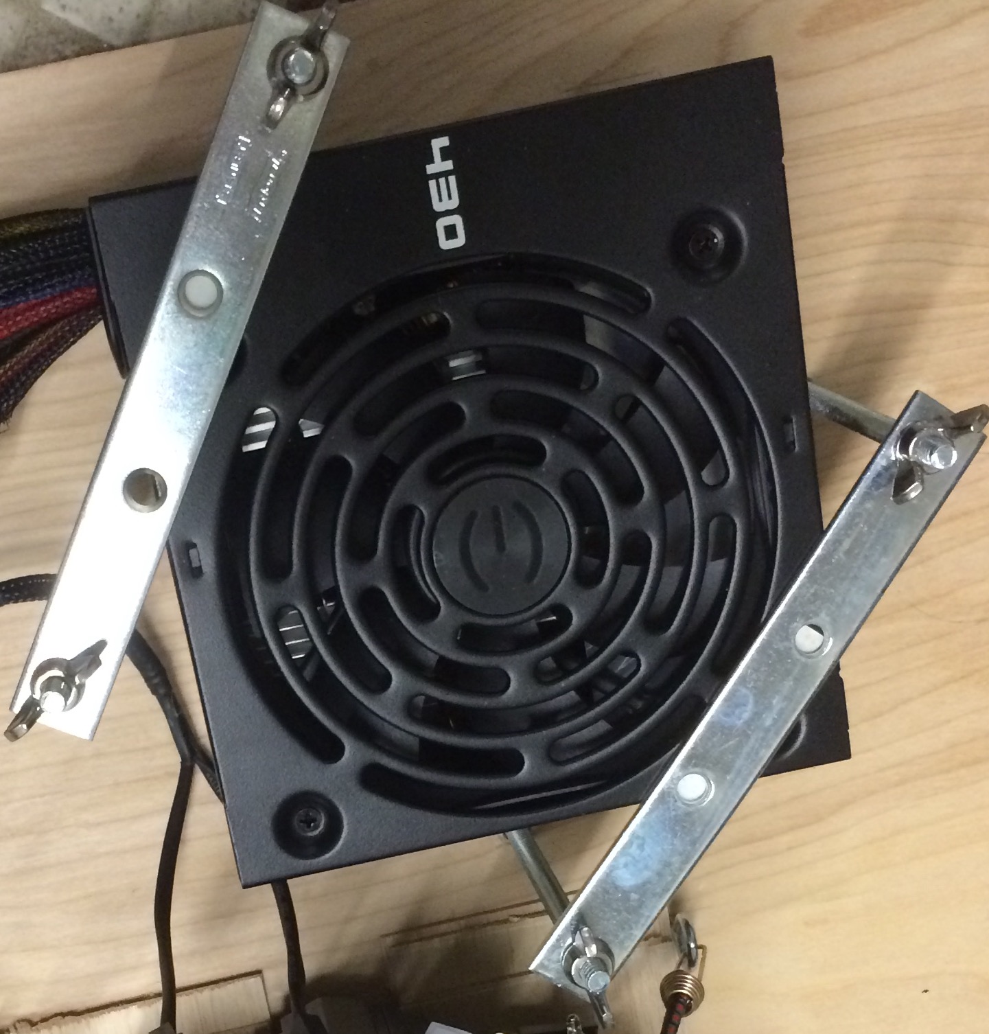 Figure 19. How mending plates should be placed over the power supply.
Step 52: Remove the power supply and CPU cooler and use a ¼ inch drill bit and drill 4 holes for the bolts next to the power supply where you marked.
- NOTE: It might be best to mark one hole where the bolt should go in one mending plate on the mounting board, drill that hole and then place the power supply where shown in the template again with the mending plate over it with a bolt through the hole on the mounting board and mark where the second hole for the other bolt should be drilled for that mending plate. This will just be to ensure the holes for the 2 bolts for one mending plate are in the right place. Repeat this process for the other mending plate as well.
Step 53: Once the holes are drilled, position the CPU cooler and power supply back on the plywood mounting board and put the bolts in from underneath the birch plywood and connect them through the holes on the mending plates with wing nuts. The wing nuts should be visible on top of the mending plates.
Step 54: Put the gooseneck arm and mount together. Twist the LED holder on the gooseneck. It should be snug.
Step 55: Place the gooseneck where it is shown on the template. Make sure this is a good spot for the gooseneck to be so that it is easy to place the LED holder around the petri dish on the CPU cooler. If not, you may need to move the gooseneck to a different spot.
Step 56: Once you are happy with the placement you can use a pencil to mark where you should drill the holes to mount it with the gooseneck, when it is facing the CPU Cooler with the petri dish.
Step 57: Use a 5/64 inch drill bit to drill the 3 holes for the gooseneck mount.
Step 58: Place the gooseneck where it was positioned before and use a screwdriver to screw in the screws, that came with the gooseneck mount, into the plywood.
Step 59: Now take everything off the plywood mounting board. Sand the plywood and trim once everything has dried with sand paper.
Step 60: Stain the mounting board (trim is now glued on plywood with wood filler if necessary and is sanded) and let it dry. We used Minwax English Chestnut Wood Finish and found it was easiest to apply with a sponge brush. Follow the instructions for application and how long it should dry that are given on the container of the type of stain you use.
Step 61: Once it is dry, put finish on over the stain. We used Minwax Fast-Drying Polyurethane Clear Satin Spray. Follow the instructions for application and how long it should dry that are given on the container of the type of finish you use.
Step 62: Once the mounting board is done and dry, mount the CPU Cooler, power supply and gooseneck again like you did before.
Step 63: Cut a 7.5 inch and 12 inch piece of tubing. Wrap the 12 inch piece around the 2 wires connecting to the LED strip and wrap the 7.5 inch piece around the wires connecting to the peltier coolers.
Step 64: If you have a 3D printer, you can download the stl file of the Lid Holder (click on the Raw button to download when you go to the link) for the petri dish lid holder or contact us through email (as25glea@siena.edu) to request that one be sent to you. Once you have the 3D printed petri dish lid holder, you can use epoxy to attach it to the plywood in the empty space. You can also fill up the empty space with logos (Siena College and CMS logo shown in picture of finished product) like we did. Refer back to the picture of our finished cloud chamber at the beginning of the instructions.
Step 65: When the petri dish lid is not being used you can put an eye cleaner cloth inside the petri dish lid holder and place the lid inside the holder. This will help prevent the lid from being scratched.